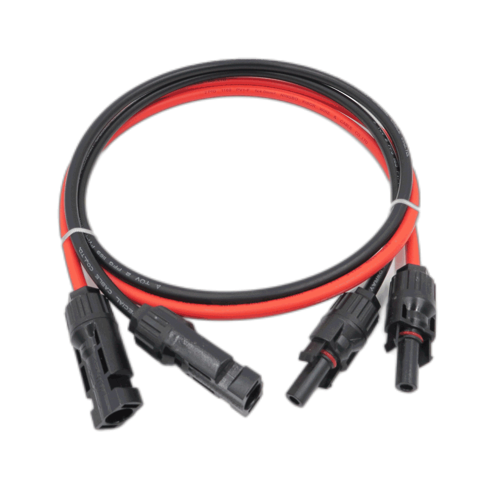
HOW TO CHOOSE THE RIGHT PV CABLE
HOW TO CHOOSE THE RIGHT PV CABLE
![]()
Why to choose photovoltaic cable?
One common factor for most of the photovoltaic power systems is outdoor use, which
involves high temperatures and high UV radiation. Single-core cables with a maximum
permissible DC voltage of 1.8 kV and a temperature range from -40°C to +90°C are
generally used 1 . The maximum conductor temperature is 120°C, and
Short Circuit Temperature of laying >250°C not more than 5 sec, with Max. Cable storage
temperature +40°C and min. installation temperature -25°C. Photovoltaic cables (PV
cable) are designed to be UV resistant and weather resistant. They can be used within a
large temperature range and are generally laid outside. Hence, only PV cables can meet
these severe conditions.
How to choose the right photovoltaic cable?
The cable conductor usually uses tinned copper or bare copper. The insulation and
jacket use s125°C XLPO which is![]() environmentally non-toxic. The jacket color is generally
environmentally non-toxic. The jacket color is generally
black or white and it can be other colors as per customers' request. For the different
standards, there are different requirements for the conductor material. For UL4703 (US),
EETS and JCS4517 (Japan), the requirement conductor material can be tinned copper or
bare copper. For TUV1169, 1990 or EN50618, the conductor must be tinned copper2 .
According to the different standards, Akatsuki offers different part numbers of PV cables to
fit the market. Below we will explain the standard in detail to help you to understand how
to choose the right PV cable for the projects.
TUV 2PfG 1169 Standard
Type of Description: PV1-F
Working Voltage: AC U0/U 600/1000V; DC 1800 V. If the cable is used in DC-systems the
rated voltage between two conductors shall not exceed the 1.5 time value of rated
1 From https://en.wikipedia.org/wiki/Solar_cable#cite_note-pv-1
2 Standard is quoted from IEC 60228.![]()
voltage U of the cable. In single-phase earthed DC-systems this value shall be multiplied
with factor 0.53 .
PV cable as a power transmission line, used in large ground plans, distributed power plans
in photovoltaic power generation system, such as monocrystalline silicon, polycrystalline
silicon solar cell components, such as Honey M, JKM320PP.
TUV 2PfG 1990Standard
Type of Description: PV1500DC-F
Working Voltage: DC 1500V. Maximum permitted voltage: DC 1,8 kV (conductor-earth,
circuit not under load)4 .
PV cable as a power transmission line, used in large ground plans, distributed power
plans in photovoltaic power generation system, such as monocrystalline silicon,
polycrystalline silicon solar cell components, such as Honey M, JKM320PP.
EN 50618Standard
Type of Description:H1Z2Z2-K
Working Voltage:AC U0/U 1000/1000V, DC 1500V. The cables specified in this standard
are particularly designed for use at the direct current (DC) sideof photovoltaic-systems,
with a nominal DC voltage up to 1,5 kV between conductors as well as between
aconductor and the earth5 .
3 From: TUV 2PfG 1169
4 From: TUV 2PfG 1990
5 From: EN 50618![]()
PV cable as a power transmission line, used in large ground plans, distributed power
plans in photovoltaic power generation system, such as monocrystalline silicon,
polycrystalline silicon solar cell components, such as Honey M, JKM320PP.
UL 4703Standard
Working Voltage 600V, 1000V, 2000V
PV cable as a power transmission line, used in large ground plans, distributed power
plans in photovoltaic power generation system, such as monocrystalline silicon,
polycrystalline silicon solar cell components, such as Honey M, JKM320PP.
EETS, JCS 4517Standard
Working Voltage DC 1500V
PV cable as a power transmission line, used in large ground plans, distributed power
plans in photovoltaic power generation system, such as monocrystalline silicon,
polycrystalline silicon solar cell components, such as Honey M, JKM320PP.
Current Rating of PV Cable
|
Current carrying capacity according to method of installation6 |
|||
|
Nominal cross sectional area |
Single cable free in air A |
Single cable on a surface A |
Two loaded cables touching, on a surface A |
|
1.5mm2( 16AWG ) |
30 |
29 |
24 |
|
2.5mm2( 14AWG ) |
41 |
39 |
33 |
|
4mm2( 12AWG ) |
55 |
52 |
44 |
|
6mm2( 10AWG ) |
70 |
67 |
57 |
|
10mm2( 8AWG ) |
98 |
93 |
79 |
6 From EN50618
|
16mm2( 6AWG ) |
132 |
125 |
107 |
|
25mm2( 4AWG ) |
176 |
167 |
142 |
|
35mm2( 2AWG ) |
218 |
207 |
176 |
Ambient temperature Conversion factor
|
up to 60℃ |
1.0 |
|
70℃ |
0.92 |
|
80℃ |
0.84 |
|
90℃ |
0.75 |
Using customers should observe the above cable carrying capacity when choosing the
appropriate cable specifications. The photovoltaic power plan commonly uses cable
specifications 4mm2~6mm2(12AWG~10AWG).